Phone: (IN) +91 80035 33335 (USA) +1 720 800 8859 Email: info@bimpactdesigns.com
Phone: (IN) +91 80035 33335 Email: info@bimpactdesigns.comAssociate company of Dhanuka Group Venture – Since 2002
Phone: (IN) +91 80035 33335 (USA) +1 720 800 8859 Email: info@bimpactdesigns.com
Construction drawings are an essential part of any construction project, providing a detailed and comprehensive visual guide and helping in planning various aspects of the building.
These drawings also communicate design ideas, dimensions, layout, and types of material specifications to the construction team (Architect, Engineers, MEP team).
Apart from helping the technical team in understanding the layout these drawings also help in seeking various project approvals.
There are several types of construction drawings, each with its own set of purposes and requirements.

Purpose of Construction Drawings
Construction drawings include detailed information on the layout of the building, the materials to be used in construction, and other important details such as (MEPF) mechanical, electrical, plumbing, and fire systems, also cover details for HVAC systems, and structural elements.
By providing this information in a visual format, construction drawings allow contractors and other construction professionals to better understand the scope of the project and ensure that the building is constructed according to the designer’s specifications.
Types of Construction Drawings
There are many different types of construction drawings, each with its own specific purpose.
Some of the most common types of construction drawings are:
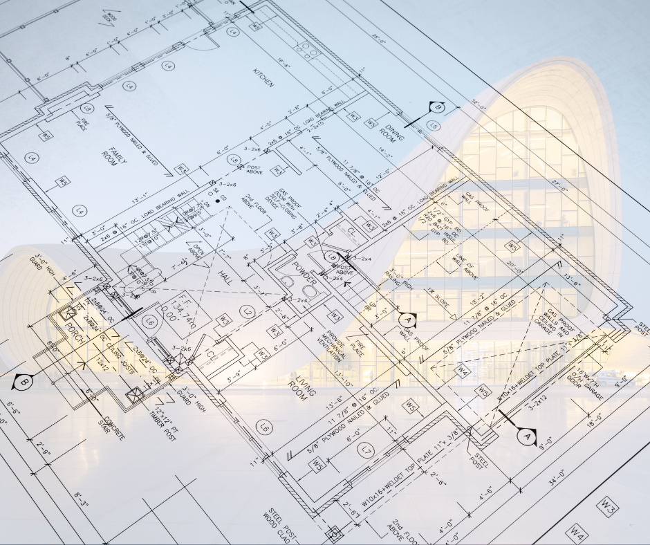
Architectural Drawings
Architectural drawings are created by architects to communicate the design intent and an overall view of a building project or a structure.
These drawings typically include floor plans, site plans, elevations, and sections.
These plan sheets are usually organized in the order of the building process.
See more about Architectural 3D Modelling.
1 Title Sheets
The title sheet serves as the cover page for a set of plans.
It typically features a front elevation view of the building and includes important information about the key players involved in the project, such as the architect, owner, builder, and major subcontractors.
2 Site Plans
The site plan is the view seen when looking directly down from above.
It is a visual representation of a space, typically viewed from a bird’s eye perspective.
It includes all walls and openings, as well as dimensions to accurately depict the size and layout of the area, commonly used in architecture and interior design to help visualize and plan out a space before construction or renovation.
3 Elevations
Each elevation is the view from one side of the construction when looking at it from the outside.
When it comes to understanding the vertical dimensions of a structure, elevation views are essential.
These views provide a picture of a building’s size, detail, and the positioning of features like windows and floor levels.
4 Floor Plans
A floor plan is a visual representation of a building’s layout, showcasing the placement of walls, doors, windows, and other architectural elements. It is typically the most detailed and informative of all plan sheets.
To ensure accuracy, the cutting plane of the floor plan should be set at a height that includes all window and door openings. This sheet provides crucial information on the size and layout of each room, as well as any electrical, HVAC, and plumbing details.
5 Cross-sectional views
It is often necessary to show the details (that are normally hidden) of an object or structure. To do this it is necessary to imagine that it has been cut through, or ‘sectioned’.
These views are essentially slices taken through the object, revealing the position and direction of the section using sectional lines. The section typically includes details of the footings, floor, walls, ceiling, and roof, giving a comprehensive understanding of the structure.
In order to make sure that the building has been designed in accordance with the code, local authorities typically demand section views.
6 Working drawings
Working drawings are essential instructions for completing a project.
These drawings are used by contractors to build the project and by suppliers to fabricate components or assemble and install them. Working drawings, along with specifications and bills of quantities, are part of the production information that designers prepare and pass on to the construction team to ensure the project is constructed accurately.
7 Single Line Plan
A single-line plan is a simplified diagram representing a room’s layout in a single line.
This line accurately depicts the configuration of the room, including the sizes of each area and the placement and labeling of doors. A line plan provides a clear and concise overview of how the entire room will be organized.
8 Landscape Drawings
Landscape drawings interpret a site’s physical characteristics and environment to design and plan outdoor spaces.
These drawings include hardscape elements like walkways and outdoor structures, as well as softscape features such as trees, flowers, and shrubs.
Landscape architecture involves working with natural materials to create beautiful and functional areas that enhance the human experience while also preserving local ecosystems.
Know more about BIM in landscape Architecture.
9 Finishing drawings
Finishing drawings and elevation drawings are closely related as they both focus on the intricate details of a project.
Finishing drawings allow the incorporation of floor patterns, false ceiling types and shapes, paint colors, plaster, textures, and other details that enhance the aesthetic value of a structure.
10 General Note
The general note section may not include any visual representations, but it is a crucial source of information for understanding the construction and design of the building.
It provides details such as by-laws, codes, length measurements, mapping forms, construction types, legends, abbreviations, and other essential information that is necessary for the proper interpretation of the plans.
11 Excavation Drawings
These drawings outline the dimensions of the excavation, including its depth, width, and length, and may also specify the method of excavation, such as trenching or tunnelling.
The drawings also outline the dimensions, depths, and slopes of the excavation area.
12 As-built drawings
During the construction process of a building project, it is not uncommon for changes to be made due to unforeseen circumstances that arise on site.
To accurately reflect what has been built, as-built drawings are often prepared either during construction or after it is complete.
13 Penetration drawings
Penetration drawings are an essential part of the design process for various systems, including structural, mechanical, electrical, plumbing, and fire protection.
These drawings provide information on the location and size of all sleeve/cores and shaft penetrations through floors and walls, including rough-in dimensions.
14 Shop Drawings
Shop drawings serve as a crucial link between the design phase and the execution phase of a construction project.
These are detailed plans that provide instructions on how to install, fit, or manufacture a particular object in the construction.
They bridge the gap between theoretical concepts and on-site implementation, ensuring that the project is executed accurately according to the intended design.
15 Installation Drawings
An installation drawing is a detailed technical drawing that provides information on how to install or assemble a particular object, system, or equipment.
It typically includes dimensions, annotations, symbols, and other relevant information to guide the installation process accurately.
16 Location Drawings
General arrangement drawings, also referred to as location drawings, provide a visual representation of the placement of various building components.
These drawings include floor plans, elevations, and sections to accurately depict the location of each element.
17 Location Plan
A location plan is a detailed map that shows the precise location of a piece of land where a building is to be constructed.
Typically, drawn to a scale of 1:5000 and includes important details such as street names, block numbers, a North pointer. It is essential for ensuring that the building is constructed in the correct location and meets all necessary regulations.
18 Record drawings
They document any changes made to the original plans during construction.
These drawings reflect any on-site alterations reported by the contractor in the as-built drawings and are compiled as a list of changes made.
19 Reflected ceiling drawings
A reflected ceiling plan is a visual representation of how the ceiling should look when viewed from the ground. It includes details such as the design of the cornice, the placement of ceiling-mounted light fixtures, and any visible column designs.
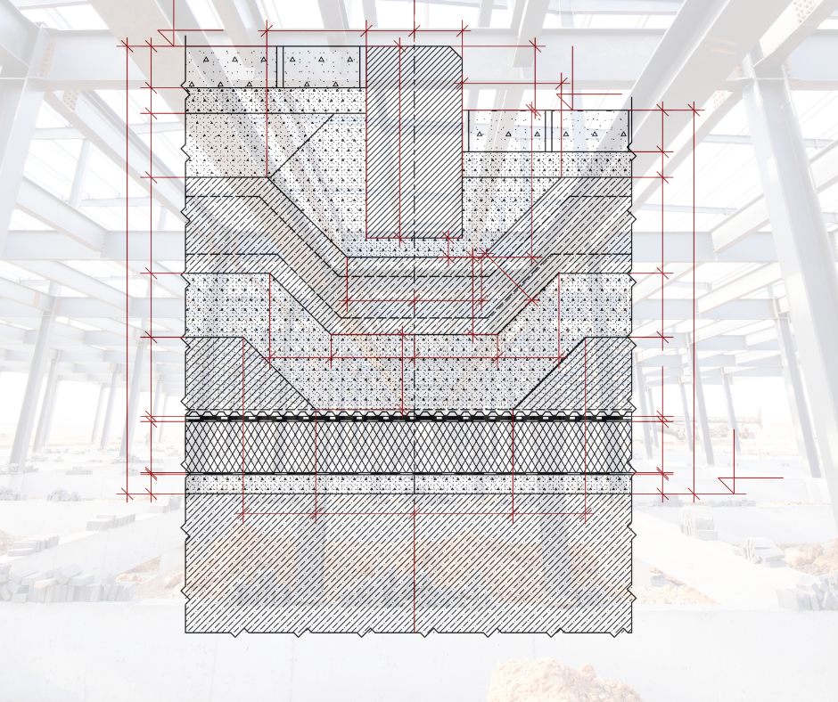
Structural Drawings
Structural drawings provide detailed specifications for the shape and placement of all components of a building or structure along with providing reinforcement drawings.
These drawings focus on the structural components, such as beams, columns, and foundations. They also provide information about the size, shape, and placement of these elements, as well as any structural connections.
Explore more about Structural 3D Modelling.
20 Engineering drawings
Engineering drawings are essential for the construction of engineered objects or components in buildings. These drawings guide contractors and engineers to ensure that the structures are constructed or placed correctly.
Read more about our MEPF 3D BIM Services
21 Column Layout
Column layout determines the precise location, dimensions, and arrangement of columns within a building’s structural framework.
It involves strategically placing columns to support the loads exerted by the structure and effectively transmitting them to the foundation.
22 Plinth beam layout
Plinth beams play a crucial role in providing stability and strength to the structure. A well-designed plinth beam layout ensures the even distribution of loads and helps prevent differential settlement.
The layout of a plinth beam is crucial to the stability and strength of a building’s foundation.
23 Lintel beam layout
Lintel beams serve a critical function in providing structural support and spanning openings such as doors and windows. It ensures the proper distribution of loads and helps maintain the integrity of the structure.
In the Lintel beam layout, you will find the correct positions, dimensions, and the number of Lintel beams on every floor.
24 Roof beam layout
Roof beams or roof joists are horizontal structural members that support the weight of the roof and transfer the load to the supporting walls or columns.
They form the framework of the roof and provide the necessary support for the roof covering, such as roofing sheets or tiles.
Roof beams are typically made of wood, steel, or reinforced concrete.
25 Roof slab layout
The roof slab serves the important function of providing precise edge information for all roof faces, floors, and other surfaces. This allows for a comprehensive understanding of the entire roof structure.
26 Block Plan
A block plan is a detailed representation of the surrounding area of the main building being constructed. It includes adjacent buildings, roads, boundaries, and other relevant components.
Block plans are typically drawn to scale, allowing for a comprehensive view of the wider area being developed.
27 Framing Plans
Framing plans depict the structural framing system of the building, including the arrangement of beams, columns, walls, and floor/roof systems.
They show the size, spacing, and connections of these elements, ensuring structural integrity and load distribution. Estimators also need this information for bidding.
28 Component drawings
Component drawings are technical illustrations provided by manufacturers to show the detailed design and specifications of individual parts of a product.
These drawings typically include markings and sub-parts, comprehensively understanding the component’s structure and function.
29 Concept drawings
Concept drawings refer to preliminary visual representations of a construction design.
These are created during the early stages of the design process and serve as a starting point for further development.
30 Assembly drawings
Assembly drawings are technical drawings that depict how various components and parts fit together to create an assembly or a larger product.
They provide detailed information on the spatial relationships, connections, and interdependencies between the individual elements within the assembly.
31 Design Drawings
Design drawings are visual representations of a design concept or idea created by designers, architects, engineers, or artists. They are used to communicate and document the details of a design to various stakeholders involved in the project, including clients, contractors, and manufacturers.
Why is Revit Modelling beneficial for Designing?
32 Foundation plans
Foundation plans are drawings that show the location, size, and shape of the building foundation. They indicate the location of footings, columns, and other foundation elements.
A foundation plan provides critical dimensions for structural support features.
Types of Electrical Drawings
33 Electrical Drawings:
Electrical drawings are used for designing and planning electrical systems.
Providing a detailed plan for installing electrical wiring, outlets, switches, and lighting fixtures in a building.
Details also include specific electrical components like transformers, panel boards, and switchgear. Electrical drawings are also useful for maintaining and troubleshooting electrical systems.
34 Schematic Drawings:
A schematic drawing is a visual representation of a system or process using symbols, lines, and interconnections. It is commonly used in engineering, electronics, and other technical fields to illustrate the components, connections, and functions of a system.
Schematic drawings typically use standardized symbols to represent various elements such as components, devices, circuits, or subsystems. These symbols help to convey information about the system’s structure, connections, and operations in a clear and concise manner.
Types of Plumbing Drawings
35 Plumbing Drawings:
Plumbing drawings depict the layout and design of the plumbing systems in a building.
They show the locations of plumbing structures, pipes, fixtures (e.g., sinks, toilets), valves and controls, and connections to other utilities such as water supply lines, sewer lines, or gas lines.
36 Drainage Drawings
Drainage drawings are technical diagrams illustrating the layout and design of drainage systems within a building or structure. These drawings provide a visual representation of how rainwater, wastewater, and other liquids will be collected, conveyed, and discharged from the property.
key elements typically included in drainage drawings are surface drainage, subsurface drainage, sanitary drainage, stormwater management, connections, and Outlets.
Fire protection drawings
Fire Protection Drawings create a roadmap for contractors throughout the construction process allowing them to visualize how the fire protection systems fit together within the space.
37 Fire Protection Drawings:
These are technical diagrams that depict the layout, design, and installation of fire protection systems within a building or structure.
These drawings outline the fire protection systems in a building, including fire alarms, sprinkler systems, and fire extinguishers. They indicate the location of these devices and their connections.
Read how BIM helps in Fire Safety
38 HVAC Drawings
HVAC drawings are detailed plans and diagrams that depict the heating, ventilation, and air conditioning (HVAC) systems.
HVAC plans include elevations, and sections of the HVAC systems, equipment schedules and specifications, ductwork and piping layouts, and details and legends.
39 Underground utility drawings
Underground utility drawings are technical documents that depict the location, type, and other relevant information about the underground utilities present within a specific area. These utilities can include pipelines, electrical cables, communication lines, water and sewer lines, gas lines, and other subsurface infrastructure.
The drawings are typically created through a process called utility mapping which involves using various techniques to identify and document the underground utilities. These techniques may include ground-penetrating radar, electromagnetic induction, vacuum excavation, and other non-destructive methods.
Miscellaneous drawings
40 Detail Drawings
It is not always possible to use drawings to a scale of 1:100 or 1:50, to provide required information.
The architect or drafter, therefore, produces more detailed drawings on a larger scale. Scales that can be used are 1:20, 1:10, or 1:5.
41 Perspective drawings
Perspective drawing is a technique used to create the illusion of depth and three-dimensionality in a two-dimensional image. By using vanishing points and other spatial cues, artists and architects can create realistic depictions of buildings and other objects.
42 Production drawings
Production drawings, manufacturing drawings, or engineering drawings, are detailed technical documents that provide instructions for the construction process. Production drawings include Geometry and Dimensions, Detailed Views, Materials and Finishes, Bill of Materials (BOM), Annotations, and Notes.
43 Technical drawings
Technical drawings are detailed and accurate illustrations of construction plans, systems, and structures. They convey technical information about the design, materials, dimensions, and other crucial details of a project.
44 Scale drawings
Scale drawings are a form of technical representation that accurately depicts the proportions and dimensions of an object or space at a reduced or enlarged size.
In scale drawings, measurements, and distances are proportionally adjusted to represent the original object or space clearly and concisely. For example, if the scale is 1:50, it means that every unit of measurement on the drawing represents 50 units in the real object or space.
45 Plans
When seeking approval for a construction project, submission drawings are a crucial component. These drawings are created in accordance with specific by-laws and regulations set forth by the governing body.
They typically include detailed elevation drawings, sectional plans, and index plans, among other important elements.
46 Model
When submitting plans for a construction project, it is necessary to create submission drawings that adhere to the regulations set forth by the governing body.
These drawings typically include detailed elevations, sectional plans, and index plans, among others, and are submitted to the relevant authorities for approval before construction can begin.
47 Presentation drawings
Presentation drawings are a crucial component of showcasing design concepts and ideas. They are often used in exhibition proposals, brochures, and even books to visually communicate the intended design.
48 Submission drawings
These drawings typically include detailed elevations, sectional plans, and index plans, among others, and are submitted to the relevant authorities for approval before construction can begin.
49 Environmental Plan
During the planning stage of any project, you must consider the impact the project will have on the environment and take action to reduce that impact.
50 Survey Drawings
Survey drawings are technical documents that depict the measurements, boundaries, features, and characteristics of a piece of land or property.
These drawings are created by land surveyors who specialize in accurately determining and documenting the physical and legal aspects of a property.
51 Orthographic working drawings
Orthographic working drawings are flat views of one face of the construction project and include plans, elevations, and sectional views.
52 Isometric Views
Isometric views provide detailed illustrations of the height, width, and depth of a piping system. They also show the location of valves, flanges, and other parts.
Conclusion and Importance of Understanding Construction Drawings
Construction drawings are an essential component of any building construction project.
Accurate construction drawings are essential for ensuring that a building meets safety codes and standards. They also ensure that the installation of systems is efficient and cost-effective.
If you need assistance with construction drawings, don’t hesitate to reach out to us.
Our team offers BIM & building construction drafting services and can assist you throughout all stages of the construction process, from pre-construction to post-construction.
Contact us today to learn more.